
Criterion uses the latest technology to develop innovative automation solutions that help our customers save time, reduce risk, and improve quality. We’ve found that 3D printing enables us to quickly—and accurately—prototype and test concepts, enabling us to keep projects on schedule and on budget. And we know that many of our customer’s engineering teams are using 3D printing to achieve the same goals.With that in mind, we thought we’d share the process we followed to determine the best way to achieve a specific goal using 3D printed parts. Read on to learn about our testing methodology, test results, and recommendations for the best method for threading bolts into 3D printed parts. The Methods Tested
 At Criterion, we’ve been perfecting the 3D printing of prototypes and production parts for more than five years. Recently, we tested methods for threading bolts into our 3D-printed parts. Since there are a few different ways to accomplish this, we printed test parts for each of three methods, with the goal of determining which one would withstand the largest pulling force.
 In all cases, printing the hole on the side of the part held more force than printing the hole in the top of the part. The side-printed holes withstood 185% as much force (almost 2x as much) as the top-printed holes. We were surprised at how much of a difference this made, but when you think about it, it does make sense. Because 3D printed parts are printed layer-by-layer, when the hole is printed in the top of the part, you are pulling “against the grain” and therefore pulling apart layers that were printed at different times, which makes it harder for them to fuse together, resulting in a weaker structure. When the hole is printed on the side of the part, you are pulling “with the grain”, pulling at plastic that was printed at the same time, in a continuous strand—and is therefore much stronger. This can be seen in the failure mechanism of the top- and side-printed parts, where each fails between layers.Since there wasn’t a large difference in the holding force of the different methods and 300 lbf is suitable for most cases involving 3D printed parts, we suggest using other characteristics to choose which method to use for a given application.
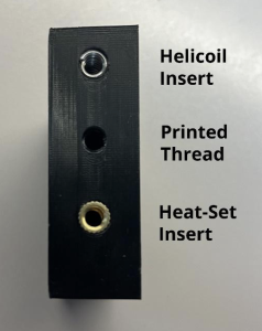 At Criterion, we’ve been perfecting the 3D printing of prototypes and production parts for more than five years. Recently, we tested methods for threading bolts into our 3D-printed parts. Since there are a few different ways to accomplish this, we printed test parts for each of three methods, with the goal of determining which one would withstand the largest pulling force.
- Method 1: 3D print a 0.313-20 threaded hole to insert a ¼-20 helical insert, or Heli-Coil
- Method 2: 3D print a ¼-20 threaded hole into the part
- Method 3: 3D print a smooth 0.316″ diameter hole for a ¼-20 heat-set insert
- 20% infill and the hole on top
- 20% infill and the hole on its side
- 30% infill with the hole on its top
- 30% infill with the hole on its side
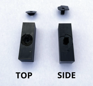
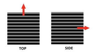 In all cases, printing the hole on the side of the part held more force than printing the hole in the top of the part. The side-printed holes withstood 185% as much force (almost 2x as much) as the top-printed holes. We were surprised at how much of a difference this made, but when you think about it, it does make sense. Because 3D printed parts are printed layer-by-layer, when the hole is printed in the top of the part, you are pulling “against the grain” and therefore pulling apart layers that were printed at different times, which makes it harder for them to fuse together, resulting in a weaker structure. When the hole is printed on the side of the part, you are pulling “with the grain”, pulling at plastic that was printed at the same time, in a continuous strand—and is therefore much stronger. This can be seen in the failure mechanism of the top- and side-printed parts, where each fails between layers.Since there wasn’t a large difference in the holding force of the different methods and 300 lbf is suitable for most cases involving 3D printed parts, we suggest using other characteristics to choose which method to use for a given application.
 - 3D printed threads are the easiest in the sense that they don’t require any additional hardware. However, if you want to take the bolt in and out of the part, the plastic threads will wear quite quickly and you may want to consider using some kind of metal thread insert. In addition, modeling the threads can be difficult to implement in some CAD software programs. We found an easy way to do this in Autodesk Inventor software and are happy to share it with you; just email us at [email protected]!
- Heat-set inserts are probably the easiest option from a CAD perspective, since you just need to make a round hole, not a threaded hole. They do require some extra equipment, namely a soldering iron, to insert. The only notable downside in function is that it can be easy to get the hole (slightly) misaligned, since the installation involves melting the plastic around the insert. If you need a precise angle on the fastener, we would recommend using one of the other two methods.
- Heli-Coil inserts are easy to use and provide a long-lasting thread with precise location and angle. The only disadvantage is that you need to be able to 3D model the thread in order to print it, and Heli-Coils often have strange OD thread types.